AS4V DC ALARM (dual or quad alarm trip; field-configurable)
Cập nhật: 2/17/2020 - Số lượt đọc: 2954
Thông tin sản phẩm
Giá:
Call
Hãng sản xuất:
M-system
Bảo hành:
Số lượt xem:2954
AS4V Plug-in Signal Conditioners M-UNIT
DC ALARM (dual or quad alarm trip; field-configurable)
Functions & Features • Provides relay outputs at preset DC input levels • Quad or dual trip • Setting and display in engineering unit values • Setpoint adjustments with the front keypad • Software lock • Adjustable hysteresis (deadband) • On-delay timer • Hi/Lo trip and energized/de-energized coil independently selectable for each setpoint • Enclosed relays • Relays can be powered by 200 V AC and 100 V DC • High-density mounting on DIN rail Typical Applications • Annunciator • Various alarm applications
MODEL: AS4V–[1][2]–[3][4]
ORDERING INFORMATION • Code number: AS4V-[1][2]-[3][4] Specify a code from below for each of [1] through [4]. (e.g. AS4V-S22-R/UL/Q) • Specify the specification for option code /Q (e.g. /C01/SET)
[1] INPUT Current Z1: Range 0 – 50 mA DC (Input resistance 100 Ω) Voltage S1: Range -1 – +1 V DC (Input resistance 1 MΩ min.) S2: Range -10 – +10 V DC (Input resistance 1 MΩ min.)
[2] OUTPUT 2: 4 points; N.O. or make contact 3: 4 points; N.C. or break contact 5: 2 points; SPDT or transfer contact 2A: 4 points; N.O. or make contact (small load current) (CE not available. Option /UL Not selectable.) 3A: 4 points; N.C. or break contact (small load current) (CE not available. Option /UL Not selectable.) 5A: 2 points; SPDT or transfer contact (small load current) (CE not available. Option /UL Not selectable.)
[3] POWER INPUT AC Power M2: 100 – 240 V AC, 50 – 60 Hz (Operational voltage range 85 – 264 V, 47 – 66 Hz) DC Power R: 24 V DC (Operational voltage range 24 V ±10 %, ripple 10 %p-p max.) P: 110 V DC (Operational voltage range 85 – 150 V, ripple 10 %p-p max.)
[4] OPTIONS (multiple selections) Standards & Approvals blank: CE marking /UL: UL approval, CE marking Other Options blank: none /Q: Option other than the above (specify the specification)
SPECIFICATIONS OF OPTION: Q (multiple selections) COATING (For the detail, refer to M-System's web site.) /C01: Silicone coating /C02: Polyurethane coating /C03: Rubber coating (UL not available) TERMINAL SCREW MATERIAL /S01: Stainless steel (UL not available) EX-FACTORY SETTING /SET: Preset according to the Ordering Information Sheet (No. ESU-1609)
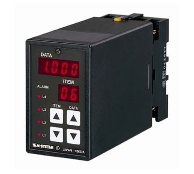
GENERAL SPECIFICATIONS Construction: Plug-in Connection: M3.5 screw terminals Screw terminal: Chromated steel (standard) or stainless steel Housing material: Flame-resistant resin (black) Isolation: Input to output to power Sampling cycle: 100 msec. User-configurable items: Front key pad • Alarm setpoint • Display range scaling • Power ON-delay time • Alarm ON-delay time • Moving average • Hi/Lo trip operation • Coil at alarm • Hysteresis (deadband) • 0 %, 100 % input setting • Latching control • Others (Refer to the instruction manual) ■ DISPLAY LED: 8 mm (.31”) 7 segment, red Number of display digits: 4 digits for DATA display; 2 digits for ITEM display Range: -1999 to 9999 (decimal point position selectable) PV indication: Input signal in engineering unit Overrange indication: LEDs blinking Power saving mode: Displays turn off if the keys are untouched for a preset time period LEDs: Red LEDs turn on when coils are energized. (L1 and L2 for 2-point alarm. L1, L2, L3 and L4 for 4-point alarm.)
INPUT SPECIFICATIONS ■ DC Current: 0 – 50 mA DC; shunt resistor attached to input terminals (0.5 W) Operational range: 0 – 70 mA DC (with 100 Ω / 0.5 W) Minimum increment: 0.1 mA Default setting: 4 – 20 mA DC ■ DC Voltage: -1 – +1 V DC for S1; -10 – +10 V DC for S2 Operational range: -1.15 – +1.15 V DC for S1; -11.5 – +11.5 V DC for S2 Minimum increment: 10 mV for S1; 100 mV for S2 Default setting: -1 – +1 V DC for S1; -10 – +10 V DC for S2
OUTPUT SPECIFICATIONS ■ Quad Alarm Relay rating: 120 V AC @ 1 A (cos ø = 1) 240 V AC @ 0.5 A (cos ø = 1) 30 V DC @ 1 A (resistive load) Maximum switching voltage(Note): 380 V AC or 125 V DC Maximum switching power(Note): 120 VA or 30 W Minimum load: 5 V DC @ 10 mA Mechanical life: 5 × 10⁷ cycles ■ Dual Alarm Relay rating: 120 V AC @ 5 A (cos ø = 1) 240 V AC @ 2.5 A (cos ø = 1) 30 V DC @ 5 A (resistive load) Maximum switching voltage(Note): 380 V AC or 125 V DC Maximum switching power(Note): 600 VA or 150 W Minimum load: 5 V DC @ 10 mA Mechanical life: 5 × 10⁷ cycles ■ Small load current type Relay rating: 30 V DC @ 1 A (resistive load) Maximum switching voltage(Note): 220 V DC Maximum switching power(Note): 30 W (resistive load) Minimum load: 1 V DC @ 1 mA Mechanical life: 5 × 10⁷ cycles
(Note): The value indicate capacity of output relay in equipment. Use within relay rating for EU and UL.
INSTALLATION Power consumption •AC: ≤ 6 VA •DC: ≤ 3.5 W Operating temperature: -5 to +55°C (23 to 131°F) Operating humidity: 30 to 90 %RH (non-condensing) Mounting: Surface or DIN rail Weight: 500 g (1.1 lb)
PERFORMANCE in percentage of FS input Setpoint accuracy (trip point accuracy): ±(0.1 % of FS + 1 digit) Display accuracy: ±(0.1 % of FS + 1 digit) Temp. coefficient: ±0.015 %/°C (±0.008 %/°F) Response time: ≤ 0.5 sec. (0 – 100 % at 90 % setpoint) Line voltage effect: ±0.1 % over voltage range Insulation resistance: ≥ 100 MΩ with 500 V DC Dielectric strength: 2000 V AC @1 minute (input to output to power to ground)
STANDARDS & APPROVALS EU conformity: EMC Directive EMI EN 61000-6-4 EMS EN 61000-6-2 Low Voltage Directive EN 61010-1 Measurement Category II (output) Installation Category II (power) Pollution Degree 2 Input to output to power: Basic insulation (300 V) RoHS Directive EN 50581 Approval: UL/C-UL general safety requirements (UL 61010-1, CAN/CSA-C22.2 No.61010-1)
EXTERNAL VIEW
Refer to the instruction manual for detailed procedures.